Figuring out how to install ram in the correct motherboard slots is the step that saves you from running half your memory speed. The right slots are not always the ones that look obvious, because labels and color codes change by board. Start with the manual, not guesswork.
As of 2026, most desktop boards use DDR4 or DDR5 modules, and JEDEC standards define the module type and voltage. Your board manual tells you which physical slots make up each memory channel. That is the map you need before you touch a stick.
Why RAM Slot Order Depends on Your Specific Board
Your CPU has a memory controller, and that controller talks to slots in groups called channels. A board can place those channels in different physical orders to make routing easier. That is why slot two on one board may be channel A, while slot two on another board may be channel B.
The board maker also chooses between daisy-chain and T-topology trace layouts. Those layouts affect which slot pairs are closest to the CPU and which are better for four-stick builds. You do not need to memorize trace theory.
You do need to trust the manual over generic internet advice.
If you are still choosing parts, run compatibility checks before buying parts and confirm your memory kit is on the board's supported list. A kit that fits physically can still fail to train at its rated speed if the board never validated it.
- One stick usually goes in the primary slot for channel A.
- Two sticks usually go in the same color pair or the slots named in the manual.
- Four sticks usually fill every slot, but the install order still matters.
- Three sticks are less common and depend heavily on the board's population rules.
How to Read the Memory Diagram in Your Manual
The manual's memory diagram is the single source of truth for slot order. It shows slot labels, channel letters, and often the recommended slots for one, two, or four modules. Match the printed labels to the white silkscreen text on the board, not just the slot colors.
Look for a table or diagram near the memory installation section. It may say things like A2 and B2 for two sticks, or A1, B1, A2, B2 for four sticks. Some boards also list maximum supported capacity per slot and per channel.
Check those numbers before installing high-capacity sticks.
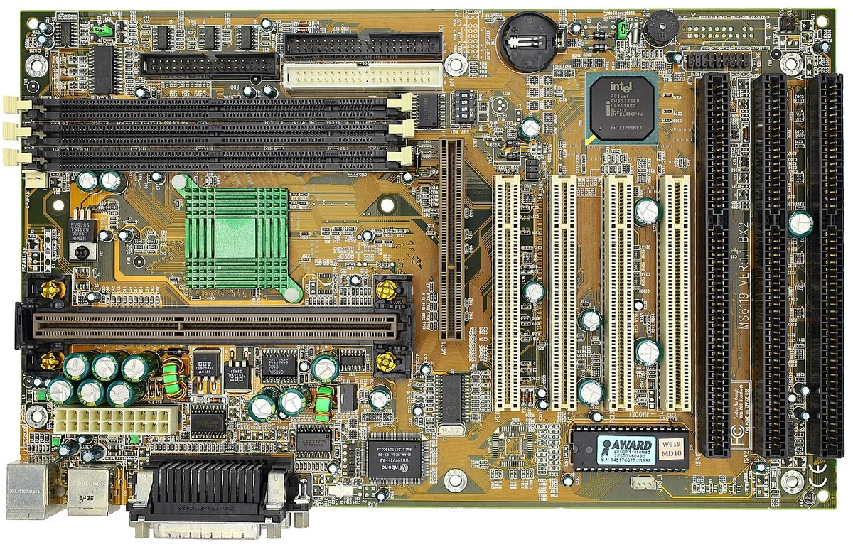
Image source: Wikimedia Commons / Mister rf (CC BY-SA)
Image source: Wikimedia Commons / Autopilot (CC BY-SA)
If you cannot find the diagram, search the PDF manual for "DIMM," "memory configuration," or "population." You can also check the motherboard QVL memory list to see tested kits and their slot requirements. Manufacturer documentation is more reliable than a forum screenshot from an older board revision.
JEDEC defines common module standards, but board makers decide how those modules connect to the CPU. That gap is why two boards with the same chipset can use different slot orders.
Visual Identifiers: Colors, Labels, and Channel Groupings
Color coding is helpful, but it is not universal. One board may use blue and black pairs, while another uses yellow and white pairs. Treat color as a clue, not the final answer.
The printed label next to each slot is the better reference.
Labels usually follow a pattern such as A1, A2, B1, and B2. The letter is the channel, and the number is the slot position within that channel. Channel A and channel B are what create dual-channel memory bandwidth.
If you install two sticks in the same channel, the system may run in single-channel mode.
Image source: Wikimedia Commons / gekkio (Joonas Javanainen) (CC BY)
| Visual Clue | What It Usually Means | What to Verify |
|---|---|---|
| Same color pair | Often the recommended two-stick slots | Manual diagram |
| A1 / A2 labels | Same memory channel | Channel grouping |
| B1 / B2 labels | Second memory channel | Slot order for four sticks |
| Notch position | Prevents wrong DDR type | Module and slot keying |
Before buying, check whether RAM is supported by your motherboard. Then match the kit's speed, capacity, and rank to the board's limits. A visually correct install cannot fix an unsupported kit.
Step-by-Step Installation for 1, 2, 3, or 4 Sticks
Power down the system, unplug it, and press the power button to discharge residual power. Work on a grounded surface and avoid carpet. If you have an anti-static wrist strap, use it.
These steps reduce the chance of damaging the module or slot.
Open the retention clips fully before inserting the stick. Align the module's notch with the slot key, then press straight down with even pressure. You should hear or feel the clip lock.
Do not force the module sideways. If it does not seat, remove it and check orientation.
- Install one stick in the primary slot named in the manual.
- For two sticks, use the recommended same-channel-pair slots.
- For three sticks, follow the manual exactly, because support varies.
- For four sticks, populate in the order shown, often alternating channels.
- Recheck that every clip is fully closed.
Good workspace prep makes the job easier, especially when the board is already in the case. Keep tools for a PC build nearby, but use only gentle pressure. A small flashlight helps you see slot labels and clip position without tilting the board.
- Do not touch the gold contacts.
- Do not install memory while the system is powered.
- Do not mix random old and new sticks without checking speeds.
- Do not leave a module half-seated.
Slot Population Rules for Intel and AMD Boards
Intel and AMD boards can use different slot naming and population habits. Some Intel boards prefer A2 and B2 for two sticks, while some AMD boards prefer A2 and B2 as well, but the exact labels still come from the manual. The point is not the brand.
The point is the board's printed memory diagram.
Trace layout also matters. Daisy-chain layouts often favor the slots farther from the CPU for two-stick builds, while T-topology layouts can be more forgiving. Four-stick builds can stress the memory controller more, especially at high speeds.
If four sticks fail to train, try two sticks first, then update the BIOS version and compatibility before retrying.
After installation, enter BIOS or UEFI and confirm the total capacity. Then enable XMP or EXPO only if the kit and board support it. Run a memory test if the system boots but feels unstable.
A clean install in the correct slots gives you the full bandwidth you paid for.
Visual Mistakes That Kill Dual-Channel Performance
The biggest visual trap is trusting slot color alone. Colors can repeat across channels, and some boards use colors that look paired but are not. Always match the printed labels to the manual diagram before you press a stick into place.
Another common mistake is filling two slots that share one channel. The system may still boot, but it can run in single-channel mode. That costs bandwidth even though the capacity looks correct in Windows.
Mixed memory kits create a different problem. Different speeds, timings, or ranks can force the board to downclock everything. Two kits with the same label on the box may still use different chips underneath.
| Mistake | What You Notice | Likely Result |
|---|---|---|
| Same-channel pair | Sticks sit next to each other | Single-channel mode |
| Wrong slot order | Clip locks, labels mismatch | Training or boot issue |
| Mixed kits | Different speeds or ranks | Downclocked memory |
| Half-seated stick | Clip not fully closed | No detection |
If a clip is blocked by a large graphics card, use a flashlight and work slowly. Do not lever the stick sideways to make it fit. Even pressure straight down protects the slot and the module.
Before mixing old and new memory, check whether your RAM is supported by your motherboard. That step catches speed and capacity limits before you blame the slot order.
Confirming the Install in BIOS and Windows
After installation, power on and watch for POST. Enter BIOS or UEFI and check the total memory capacity first. Then look for a channel mode or memory information screen that shows dual-channel, flex mode, or single-channel status.
If the capacity is wrong, remove power and reseat each module. Test one stick at a time in the primary slot. This isolates a bad stick, a bad slot, or an unsupported combination.
In Windows, open Task Manager and check the memory tab. Tools like CPU-Z can also show channel mode and module details. If everything looks right but the system is unstable, run a memory test before enabling an overclock profile.
What If BIOS Shows Only Half the Capacity?
Check the slot order first, then reseat every module with even pressure. Test each stick alone in the primary slot, verify the kit against the memory QVL, and update the BIOS if needed. Unsupported combinations can look like a hardware failure.
Enable XMP or EXPO only after the base configuration is stable. These profiles raise speed and voltage, so they can expose weak slot placement or an unstable kit. If training fails, return to the manual's recommended two-stick layout first.
Quick Reference Card for Common Slot Layouts
Use this card as a starting point, not a replacement for the manual. Board labels, channel grouping, and trace layout still decide the final answer. When in doubt, follow the printed diagram over any generic rule.
| Stick Count | Common Pattern | Notes |
|---|---|---|
| 1 stick | A2 or the primary slot | Check the manual label |
| 2 sticks | A2 and B2 | Often the same color pair |
| 3 sticks | A1, A2, and B2 | Board-dependent support |
| 4 sticks | A1, B1, A2, B2 | Follow printed order |
Two-stick builds are usually the easiest path to stable dual-channel performance. Four-stick builds can work well, but they place more load on the memory controller. High-speed kits may need a BIOS update or a looser timing profile when all four slots are filled.
If you are planning a full build, compatibility checks before buying parts help prevent slot and speed conflicts. A kit that fits physically still has to match the board's supported speeds and ranks.
Frequently Asked Questions
Which slots should I use for two RAM sticks?
Use the slots named in your motherboard manual, often A2 and B2 on many boards. They may share the same color, but color alone is not proof. The goal is to place one stick in each memory channel so dual-channel mode can work.
Can I install RAM in any empty slot?
You can physically install it, but performance and stability may suffer. The board expects a specific population order for each stick count. Installing in the wrong slot can force single-channel mode or cause training problems.
Why is my PC only using half my RAM?
The most common causes are wrong slot pairing, a half-seated module, or a mixed kit that downclocked. Reseat the sticks, check the manual diagram, and test one module at a time. Also verify the kit against the board's supported memory list.
Do RAM slot colors mean the same thing on every board?
No. Color coding is a helpful clue, but manufacturers use different color schemes. Always trust the printed slot labels and the memory diagram in the manual.
Colors can change between board revisions or product lines.
Should I enable XMP after installing RAM?
Enable XMP or EXPO only after the system boots cleanly at default settings. Then confirm the new speed in BIOS and test stability in Windows. If training fails, return to the manual's recommended slot order before changing timings.