How to connect motherboard power cables is mostly a matching exercise, not a guessing game. The two big connectors on a standard board are the 24-pin ATX main power and the EPS12V CPU power, and each one only fits one way. If you slow down and read the shape before pushing, you avoid the bent pins that ruin a build.
Manufacturer specifications indicate that a fully seated 24-pin ATX connector and an EPS12V connector are needed for a normal POST. The Intel ATX12V Power Supply Design Guide defines the 24-pin main connector, while board manuals show the exact CPU power socket. As of 2026, most full-size ATX boards still use one 24-pin and one 8-pin EPS connector.
Why Visual Cues Matter When Connecting Motherboard Power Cables
Photos and diagrams help because these connectors look similar at a glance. A PCIe 6+2 plug and an EPS 8-pin plug can sit side by side in a modular PSU bag. The shape, keying notch, and clip position are what tell you which one belongs on the board.
A good build photo would show the 24-pin socket near the right edge and the EPS socket near the top-left CPU area. It would also show the clip facing the latch side, not the wire side. That one detail saves a lot of bent pins.
In our research, the most common first-build mistake is pushing by force instead of checking fit. If the plug needs a hard shove, stop. Rotate it 180 degrees and check the notch again.
Identify the Two Main Motherboard Power Connectors: 24-Pin ATX and EPS12V
The 24-pin ATX main power feeds the board's general logic, slots, and storage. The EPS12V connector feeds the CPU voltage regulator modules. Both are required on most gaming PCs, and neither should be confused with GPU power.
A 20+4 pin connector is the same thing split into two pieces. The 20-pin part covers older boards, and the 4-pin tail fills the gap on modern ATX boards. Snap the two halves together before insertion so they act like one 24-pin plug.
| Connector | Pin Count | Main Job | Visual Cue |
|---|---|---|---|
| 24-pin ATX | 24 or 20+4 | Powers motherboard and expansion slots | Large rectangular plug with one angled corner |
| EPS12V | 8 or 4+4 | Powers CPU VRMs | Smaller plug with a latch and squared keying |
| Legacy P4 | 4 | Older CPU power | Half of an EPS plug |
If you are still checking PSU compatibility before buying, confirm that the PSU includes both a 24-pin cable and an EPS cable. Some small or older units only include one.
Tell EPS12V Apart from PCIe, 6+2, and 12VHPWR Connectors
EPS12V plugs go into the motherboard CPU power socket. PCIe plugs go into the graphics card. A 6+2 pin PCIe plug is not an EPS plug, even when the plastic shape looks close.
The keying and wire layout differ.
A 12VHPWR or 12V-2×6 connector is for high-power GPUs, not motherboards. It is a flat 12-pin plug with sense pins. Do not force it into an 8-pin EPS socket, because the pin arrangement is different.
The safest habit is to read the cable label before every insertion. Modular PSU cables are often labeled EPS, PCIe, or SATA. If the label is missing, trace the cable back to the PSU connector group and match the socket shape.
For a newer graphics card, PCIe compatibility issues in gaming PCs explained can help you sort GPU power from board power. Keep those cables in separate piles while you build.
Step-by-Step: Seating the 24-Pin ATX Main Power Connector
Start with the PSU unplugged and the board resting on a non-conductive surface. Hold the plug by its plastic body, not the wires, and line up the angled corner with the socket. The retention clip should face the latch side of the socket.
Push straight down with even pressure until you hear or feel a click. The connector should sit flush with the socket housing. If one side stays raised, release it and reseat from the other end.
Use this short checklist before moving on:
- The 20+4 halves are snapped together.
- The angled corner matches the socket.
- The clip is on the correct side.
- The plug is fully flush.
- No pins are bent or exposed.
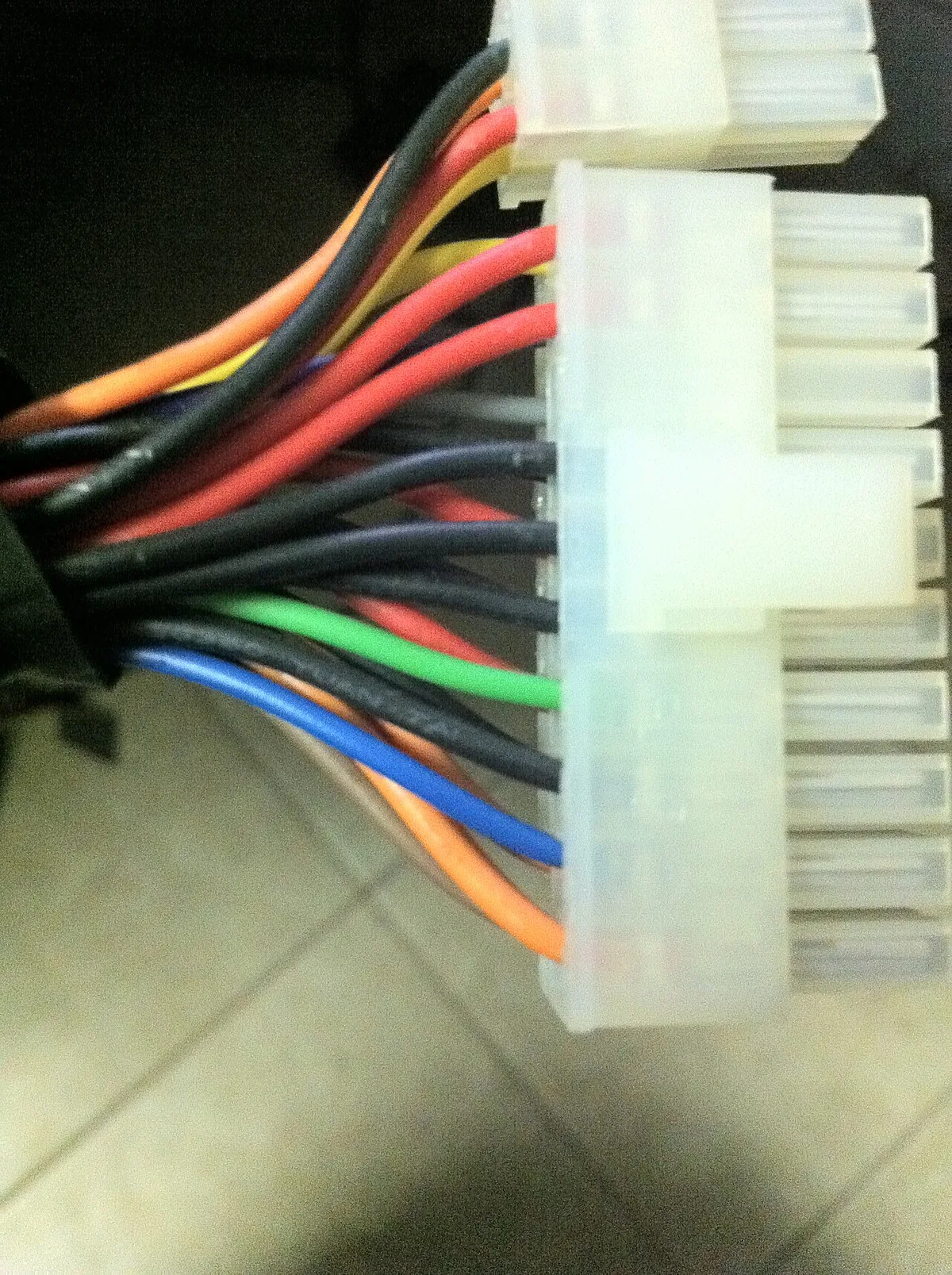
Image source: Wikimedia Commons / Rhorton4549 (CC BY-SA)
A photo of a 24-pin plug would show the locking tab near the top edge. That tab should snap into the socket's latch. If it does not click, the plug is usually rotated or not fully seated.
If you are preparing your workspace before the build, keep the manual open to the power connector page. It is easier to compare the diagram while you are holding the cable.
Step-by-Step: Seating the EPS12V CPU Power Connector
Find the CPU power socket near the top of the motherboard, usually above or beside the CPU socket. It may be labeled CPU_PWR, EPS, or EATX12V. On some boards it sits at the top-left edge, which makes cable routing tighter.
Match the 8-pin or 4+4 plug to the socket. The 4+4 version splits into two halves that sit side by side. Both halves must be present for a standard 8-pin socket, and both retention clips must click.
Push straight down until the latch engages. Do not rock the connector side to side, because that can bend pins inside the socket. If the cable is short, route it through the top grommet before seating it.
A common visual mistake is inserting only one half of a 4+4 plug. The board may still power on in some cases, but it is not a correct or stable connection. Seat both halves every time.
If you have already installed the processor first, keep the CPU area clear while routing the cable. That reduces the chance of snagging the cooler or bending the socket pins.
Routing and Retention Checks That Prevent No-POST Builds
Before first boot, trace each cable from socket to PSU. A cable can be plugged in but still loose at one end. That loose end is enough to cause a no-POST state or random reboot.
Check the retention clip first. It should be fully latched, not half-clicked. Then look for a gap between the connector body and the socket housing.
If you see daylight, reseat it.
Route the 24-pin cable through the right-side grommet or cable channel. Keep it away from fan blades and sharp case edges. A cable pinched under the motherboard can short traces or prevent the board from sitting flat.
The EPS cable often has the harder path. On top-mounted PSU cases, it may need to run across the top panel. Use the CPU cutout or top grommet, then secure it with a Velcro strap.
Do not overtighten zip ties, because they can deform sleeving and strain the crimped pins.
After routing, do a gentle tug test. Hold the connector body and pull lightly. It should not move.
If it slips, the latch did not engage.
Debug LEDs or Q-codes help after power-on. A CPU or DRAM light often points to missing EPS power. If the board has no lights, listen for beep codes and check the PSU switch.
If the system does not POST, shut down, unplug, and reseat both power connectors. Many builders find one half of a 4+4 plug was not seated. That small gap is enough to break the 12V rail.
If you are still planning the build order, the correct assembly sequence can help you cable before the cooler blocks access.
Common Visual Mistakes That Bend Pins or Prevent Boot
The biggest mistake is treating "almost fits" as "fits." Motherboard power connectors are keyed, so a wrong plug usually stops before full insertion. Forcing it bends pins or cracks the housing.
A second mistake is inserting a PCIe 6+2 plug into the EPS socket. The two can look alike in a parts bag. The EPS socket is on the motherboard near the CPU, while PCIe plugs belong on the GPU.
Another common error is leaving the 20+4 connector split. The 4-pin tail can hang loose and create an intermittent connection. Snap it into a single 24-pin shape before insertion.
4+4 EPS plugs cause their own errors. Builders often seat one half and forget the second. The board may show signs of life, but the CPU rail is not fully powered.
Always seat both halves and confirm both clips click.
Cables can also be installed backward in the routing path. A 24-pin cable twisted 180 degrees may still reach, but the retention clip points the wrong way. That makes removal harder and can stress the wires.
Bent pins are not always visible from above. Shine a flashlight across the socket at an angle. If a pin leans, do not power on.
Straighten it carefully with fine tweezers or replace the cable.
If you are installing a CPU cooler after cabling, leave extra slack near the socket. Tight cables pull on the connector when the cooler is mounted.
Modular PSU Cable Compatibility and Safety Rules
Modular and semi-modular PSUs use detachable cables. That is convenient, but the cable pinout is tied to the PSU model. A cable from one brand or series can fit physically and still be wired differently.
Never mix modular cables between PSUs. Even cables that look identical can route 12V, 5V, or ground to different pins. That mismatch can damage the motherboard, GPU, or PSU.
Use only the cables that came with the PSU. If you need longer or sleeved cables, buy a kit made for that exact model. Manufacturer specs confirm compatibility before purchase.
Non-modular PSUs avoid this risk because the cables are fixed. The tradeoff is more cable clutter in the case. Semi-modular designs fix the main 24-pin and EPS cables while allowing optional PCIe and SATA cables.
Safety starts before touching anything. Unplug the PSU and press the power button to discharge residual charge. Handle the board on an anti-static mat or grounded surface.
Do not modify cable pinouts yourself. Cutting, repinning, or splicing can void warranty and create a fire risk. If a cable is damaged, replace it with an approved part.
For a deeper check before buying, PSU compatibility for a gaming PC covers wattage, connectors, and cable sets. That step prevents most cable mismatches.
The Intel ATX12V Power Supply Design Guide defines the connector and rail expectations. Manufacturer documentation is the final word for a specific PSU.
Real-World Build Scenarios: Standard ATX, SFF, and Dual-EPS Systems
In a standard mid-tower build, cable routing is straightforward. The 24-pin usually reaches the right edge with little tension. The EPS cable may need a gentle curve across the top, but most full-size cases have enough room.
Small-form-factor builds change the problem. Short cables can be too short for a top-mounted CPU socket. A 450 mm EPS cable may not reach comfortably in a mini-ITX case.
Plan the PSU orientation before seating the CPU cooler.
Dual-EPS systems add a second connector. High-end boards and workstations may require two 8-pin CPU power connectors. Both must be seated and both clips must click.
One missing EPS plug can cause unstable boost behavior or no POST.
Cable length matters more than many builders expect. A 24-pin cable around 450 mm is common. EPS cables often run 600 to 700 mm.
Check these numbers against your case layout before final assembly.
In a cramped build, route the EPS cable before installing tall memory or a large cooler. That keeps the cable path clean and reduces strain. A mini-ITX compatibility plan helps here.
For workstation boards, label the primary and secondary EPS cables. Some PSUs ship two identical cables. Mixing them with GPU cables is easier in a crowded case, so keep them separated.
| Build Type | Common Cable Challenge | Practical Fix |
|---|---|---|
| Standard ATX | EPS routed across top panel | Use top grommet and Velcro |
| SFF | Short EPS cable | Plan PSU orientation early |
| Dual-EPS | Two identical cables | Label primary and secondary |
Frequently Asked Questions
Do I need both the 24-pin and 8-pin connectors?
Yes. The 24-pin ATX powers the motherboard and slots. The 8-pin EPS powers the CPU voltage regulators.
Most gaming PCs need both for a normal POST.
Can I use a 4-pin CPU connector on an 8-pin socket?
Sometimes, but it is not ideal. A 4-pin plug covers only half the socket. Use a native 8-pin or 4+4 connector when possible for stable CPU power.
Why does the PC not POST after connecting power?
A loose 24-pin or EPS connector is a common cause. Reseat both connectors and confirm both clips click. Also check for a half-seated 4+4 plug.
Are modular PSU cables interchangeable between brands?
No. Modular cable pinouts vary by brand and model. Using the wrong cable can damage hardware even if it physically fits.
Can I force a connector that almost fits?
No. Keying should stop a wrong connector before full insertion. Rotate or recheck the plug instead of pushing harder.
What if the EPS cable is too short?
Reroute it through a top grommet or cable channel. Do not stretch the cable or leave it under tension. A model-specific extension cable is the safer fix.
1 thought on “How to Connect Motherboard Power Cables: Step-by-Step”
Comments are closed.