Learning how to install a cpu into a motherboard is one of those tasks that looks intimidating until you actually do it. The good news is that modern sockets are designed to prevent most serious mistakes, as long as you know what to look for. This guide walks you through every visual cue and physical step so you can seat your chip with confidence.
According to manufacturer specifications from Intel and AMD, a properly seated CPU requires zero force beyond the socket's locking mechanism. The real challenge isn't strength. It's alignment, orientation, and knowing when something feels wrong.
Let's start with the single most important step before you even touch the processor.
how to install a cpu into a motherboard
Align the CPU's triangle marker with the socket's triangle marker. Lower the chip gently into the socket. Close the retention lever without forcing it.
Apply a small amount of thermal paste. Mount the cooler evenly. Connect the fan header.
Power on and check BIOS.
Why You Can't Install a CPU by Reading Alone
Text descriptions of pin alignment, socket lever resistance, and cooler mounting pressure only get you so far. A diagram showing the golden triangle on a processor die communicates more in two seconds than a paragraph ever could. That's why this guide leans heavily on visual cues you can actually see.
The physical feedback matters too. When you lower a CPU into its socket, you should feel almost nothing. No click, no snap, no resistance.
If you feel pressure, something is wrong. A bent pin on an AMD chip or a misaligned notch on an Intel socket will fight you. That resistance is your warning signal.
Many first-time builders describe the process as feeling "too easy." That's actually the correct sensation. The socket is designed as a zero-insertion-force interface. The retention lever does the work of locking the chip in place.
Your job is simply to position it correctly and let gravity do the rest.
This is also why we recommend having a magnifying glass or your phone camera handy. The tiny alignment triangles on both the CPU and socket are easy to miss under dim lighting. A quick photo zoomed in can confirm orientation before you commit to closing the lever.
Once that lever locks down, damage becomes very likely.
If you're building in a tight mini-ITX layout, the cramped quarters make visual confirmation even harder. Our guide on planning component compatibility for compact builds covers spatial challenges that directly affect how easily you can see and reach the socket during installation.
Identifying Your Socket Type Before Touching Anything
Your motherboard's socket type determines everything about how the CPU physically installs. Intel uses LGA (Land Grid Array) sockets where the pins live on the motherboard. AMD uses PGA (Pin Grid Array) on older platforms and LGA on newer AM5 designs.
The installation method differs significantly between them.
Check your motherboard manual or the silkscreen printing near the socket. You'll find the socket designation printed directly on the board. Common current sockets include LGA 1700, LGA 1851, and AM5.
Older builds might use LGA 1200, AM4, or even legacy sockets like LGA 1151.
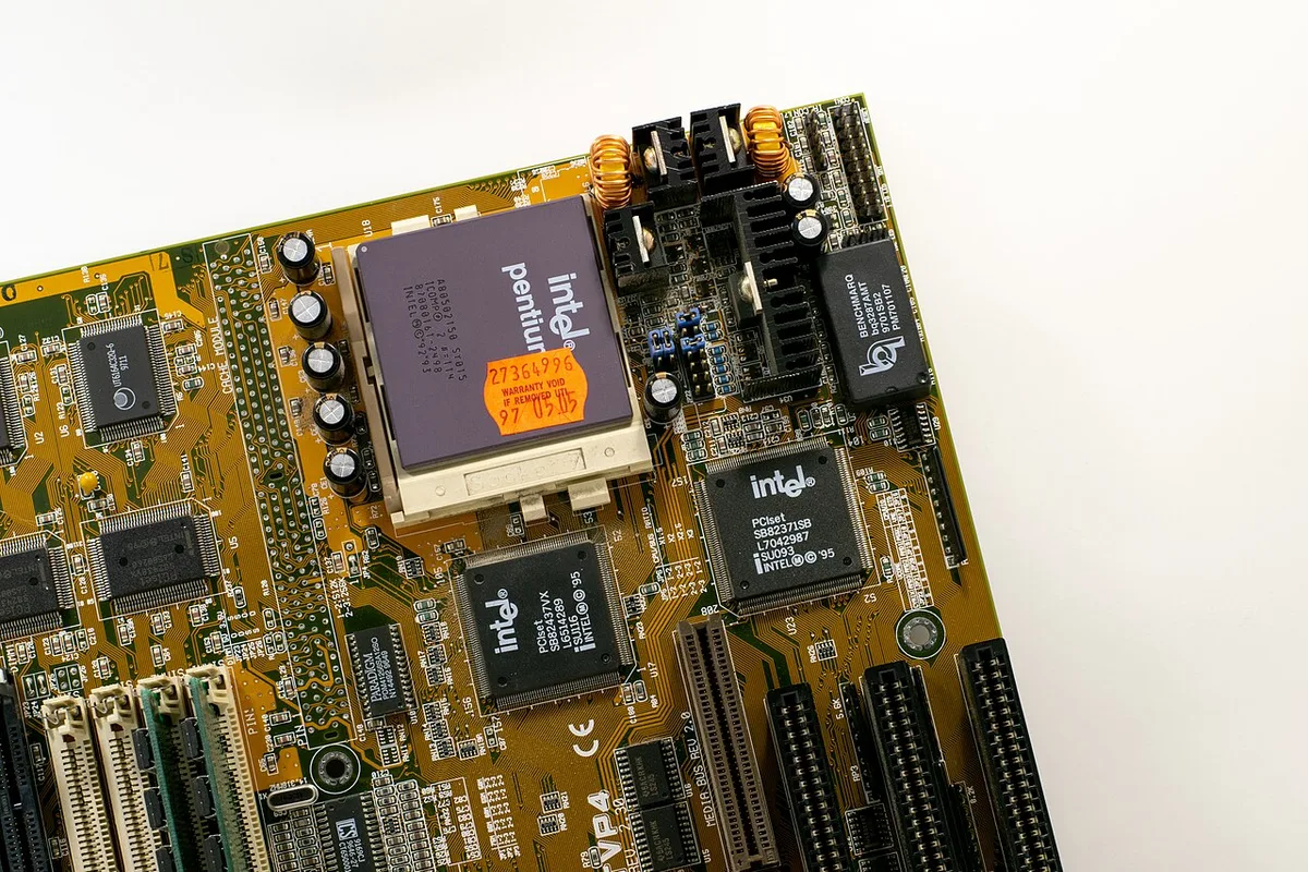
Image source: Wikimedia Commons / Oligopolism
Before you even open the CPU box, verify that your processor matches the socket. A CPU with the wrong socket type simply won't fit. The notches won't align, and forcing it will destroy the chip or the board.
This is the single most common preventable mistake in PC building.
If you're upgrading an existing system, your motherboard might need a BIOS update before it recognizes a newer processor. Our article on how BIOS version impacts component compatibility explains this in detail. Always check your motherboard manufacturer's CPU support list for your specific model.
| Socket Type | Pin Location | Locking Mechanism | Common Platforms |
|---|---|---|---|
| Intel LGA 1700 | Motherboard | ILM lever + load plate | 12th-14th Gen Core |
| Intel LGA 1851 | Motherboard | ILM lever + load plate | Core Ultra 200S |
| AMD AM5 | Motherboard | PGA-style lever + frame | Ryzen 7000/9000 series |
| AMD AM4 | CPU | Lever + retention arm | Ryzen 1000-5000 series |
The table above covers the sockets you're most likely to encounter as of 2026. Legacy platforms like AM3+ or LGA 775 still exist in older machines but follow similar principles with different lever designs.
The Critical Visual Cues: Triangles, Keys, and Notches
Every CPU and every socket has alignment markers. On Intel processors, look for a small gold triangle in one corner of the Integrated Heat Spreader. The matching triangle sits on the socket itself, usually in the bottom-left or top-right corner depending on orientation.
These must line up perfectly.
AMD processors use a similar system. The triangle marker appears on the corner of the CPU substrate. The socket frame has a corresponding triangle.
On AM4 and AM5, there's also a small notch on one edge of the CPU that mates with a bump on the socket frame. Both must align simultaneously.
The notches serve a dual purpose. They prevent 180-degree rotation, which would place pins over the wrong contacts. They also act as a physical key.
If the notch doesn't seat cleanly into its slot, the CPU is rotated or shifted. Never force it.
Here's what diagrams show that text can't fully convey. The CPU should sit flat on the socket with zero gap between the substrate and the socket frame. If one corner is slightly raised, a pin is misaligned or a foreign object is in the socket.
Remove the chip and inspect both surfaces under good light.
Checking whether your CPU and motherboard are actually compatible takes minutes and prevents hours of frustration. Our step-by-step compatibility guide covers this verification process in detail.
For Intel LGA sockets, the load plate has its own alignment notches. The plate must close flat and even. If one side catches before the other, stop immediately.
Back off, reseat the CPU, and try again. A tilted load plate means the chip shifted during closure.
Lighting matters more than people realize. Work under a bright, even light source. A desk lamp with a cool white bulb works well.
Warm yellow light can mask the gold triangle on the IHS. If you're building at night, consider a headlamp for hands-free illumination.
Step-by-Step: Seating the Chip Without Damage
Follow this sequence exactly. Each step builds on the previous one, and skipping ahead risks bending pins or cracking the silicon die.
- Ground yourself. Touch the metal case frame or wear an anti-static wrist strap. ESD damage isn't always immediate. It can degrade a processor over weeks of use.
- Open the socket. Lift the retention lever fully vertical. On Intel, the load plate swings open. On AMD AM4/AM5, the frame lifts slightly.
- Inspect the socket. Look for bent pins (PGA) or debris in the LGA contacts. A single bent pin can kill a memory channel or PCIe lane.
- Orient the CPU. Match the triangle on the processor to the triangle on the socket. Verify the notches align.
- Lower the chip. Hold it by the edges only. Let it drop from about one centimeter above the socket. It should seat with zero resistance.
- Verify flatness. All four corners should touch the socket frame evenly. No rocking, no gaps.
- Close the lever. Apply steady, even pressure. On Intel, the load plate clicks into place under the retention hook. On AMD, the lever presses down until it locks horizontally.
- Check for gaps. The CPU should be invisible under the load plate. Any visible edge means improper seating.
The lever will require noticeable force on Intel sockets. This is normal and designed. The load plate's spring mechanism clamps the chip against the contacts.
What should never happen is grinding, clicking, or a lever that won't reach the locked position.
If the lever stops halfway, don't push harder. Remove the CPU, inspect for bent pins, and reseat. Forcing a stuck lever bends contacts permanently.
This is where most installation damage occurs.
After seating, resist the urge to test-fit the cooler immediately. Take a breath, check your alignment one more time, and then proceed to thermal paste application.
Thermal Paste Application: Less Is More (Visually)
Thermal paste fills microscopic gaps between the CPU's heat spreader and the cooler's base plate. Air is a terrible thermal conductor. Paste replaces those air pockets with a material that transfers heat efficiently.
Too much paste acts as an insulator. Too little leaves air gaps.
Manufacturer specifications from major cooler brands like Noctua and Thermal Grizzly recommend a pea-sized amount for most desktop processors. That's roughly 0.3 to 0.5 milliliters. Spread methods work too, but they risk trapping air bubbles under the cooler base.
The visual cue for correct application is simple. After mounting the cooler, remove it and inspect the paste spread. You want about 90 percent coverage across the heat spreader.
The center should be fully covered. The edges can have slight gaps without affecting performance significantly.
Our detailed guide on how thermal paste works explains the science behind different formulations, including ceramic, metal, and liquid metal options. Liquid metal requires special handling and isn't recommended for first-time builders.
| Application Method | Amount | Coverage Risk | Best For |
|---|---|---|---|
| Pea dot (center) | Pea-sized | Low air bubble risk | Most users |
| Line (vertical) | Rice grain width | Moderate | Rectangular dies |
| Spread (manual) | Thin even layer | High air bubble risk | Experienced builders |
| X pattern | Four small dots | Low | Large heat spreaders |
Clean the old paste off completely before reapplying. Use 90 percent or higher isopropyl alcohol and a lint-free microfiber cloth. Let the surface dry for at least 60 seconds.
Any residue creates an uneven thermal interface.
Pre-applied paste on stock coolers is perfectly fine for most users. Don't remove it to apply your own. The factory application is calibrated for that specific cooler design.
Removing it and reapplying introduces unnecessary risk.
If you're replacing paste on an existing build, check our guide on how often thermal paste should be replaced. Most users only need to reapply every two to three years unless temperatures climb unexpectedly.
Mounting the Cooler: Torque Patterns and Clearance Checks
Mounting pressure matters as much as paste amount. The cooler base must touch the entire heat spreader evenly. Uneven pressure creates hot spots and can stress the socket.
Start with the backplate. Most aftermarket coolers use a metal backplate behind the motherboard. Align the mounting holes before placing the cooler.
Drop the screws through the cooler and thread them into the backplate by hand first.
Tighten in a cross pattern. Turn each screw a quarter turn, then move to the opposite corner. Repeat until all screws are snug.
Stop when resistance increases sharply. Overtightening can crack the substrate or bend the board.
Check clearance before final tightening. Tall RAM modules, VRM heatsinks, and case side panels can block a large air cooler. Our guide on cooler and case fit helps you spot these conflicts before mounting.
Visual check: the cooler base should sit flat with no visible tilt. The gap between cooler and heat spreader should be invisible. If one corner lifts, loosen and reseat.
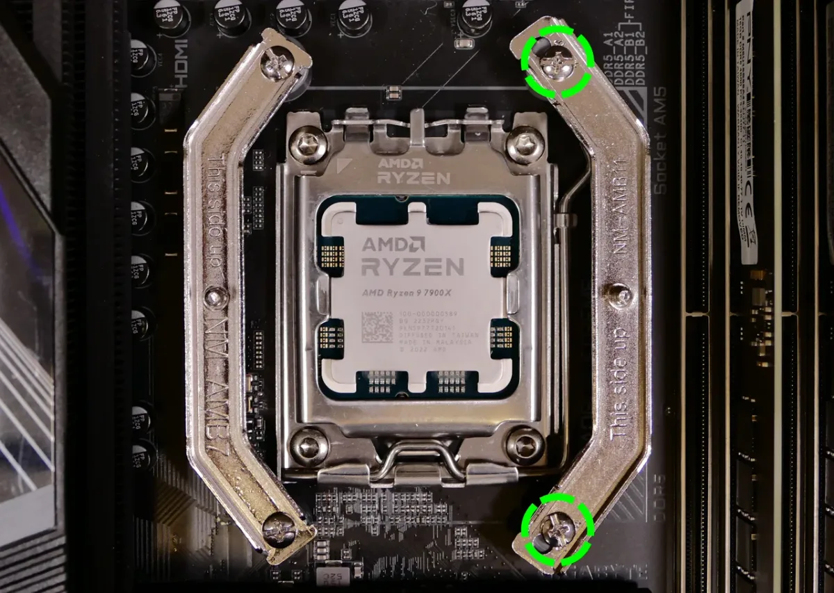
Image source: Wikimedia Commons / System76 (CC BY-SA)
| Cooler Type | Mounting Style | Visual Cue |
|---|---|---|
| Stock cooler | Push pins | Audible click at each corner |
| Air tower | Spring screws | Even gap on all sides |
| AIO liquid | Standoffs and thumb screws | Flush contact at base |
Connect the fan cable to the CPU_FAN header. For AIO pumps, use the PUMP or AIO_PUMP header if available. A disconnected fan can trigger a boot error or cause rapid overheating.
Manufacturer documentation from Intel and AMD covers header placement for specific boards.
Common Visual Mistakes That Kill Components
Most installation failures leave visible clues. Bent pins look like tiny crooked wires in the socket. Scratched LGA pads appear as silver lines on the motherboard contacts.
A cracked die shows as a hairline fracture across the black silicon.
Excess thermal paste is easy to spot. It squeezes out beyond the heat spreader edges. Clean it with isopropyl alcohol and reapply.
Too much paste insulates instead of conducting heat.
An uneven cooler base leaves one corner raised. This often comes from tightening screws in a circle instead of a cross pattern. Loosen all screws and re-torque evenly.
Dust or fingerprints on the contact surfaces also cause problems. Clean both the heat spreader and cooler base before assembly. Oils from skin reduce thermal transfer.
Poor contact can lead to a heat-related slowdown, where the CPU reduces clock speed to avoid damage. If temperatures spike under light load, power down and inspect the mounting.
Post-Install Verification: BIOS and Temperature Checks
Power on and watch the debug LEDs or POST codes. A successful boot shows CPU, DRAM, BOOT, and VGA lights cycling. If the CPU light stays lit, reseat the processor and check power cables.
Enter BIOS and confirm the model name appears correctly. Check the CPU temperature at idle. Most modern processors idle between 30 and 45 degrees Celsius with a stock cooler.
Compare your readings against gaming temperature limits to judge whether the thermal interface is working. A spike above 90 degrees under load suggests poor paste contact or mounting pressure.
Verify fan speeds in the hardware monitor. The CPU fan should report RPM immediately. Zero RPM means a loose cable or wrong header.
Fix this before running any workload.
Memory training may take longer after a CPU swap. Wait patiently. Interrupting training can cause boot loops.
If the system hangs, power cycle once and let it retry.
Troubleshooting Boot Failures Based on Physical Symptoms
No display with a lit CPU debug LED usually means improper seating. Remove the cooler, lift the lever, and inspect for bent pins or debris. Reseat and retry.
A lever that won't lock suggests misalignment. Check the triangle markers again. On Intel, ensure the load plate sits flat before closing.
On AMD, verify the frame drops evenly.
If the system powers on but shuts off after seconds, the cooler may be over-tightened. Loosen each screw slightly and test again. Excessive pressure can cause short circuits or cracked silicon.
Random reboots under load often trace back to poor thermal contact. Check paste coverage by removing the cooler. Reapply if coverage is patchy or air bubbles appear.
BIOS updates can resolve compatibility issues with newer processors. Our guide on BIOS compatibility explains when an update is needed and how to apply it safely. Always confirm a socket match before assuming a BIOS issue.
Frequently Asked Questions
Can you install a CPU without thermal paste?
No. Thermal paste fills microscopic gaps between the heat spreader and cooler base. Without it, air pockets insulate the chip.
Temperatures rise quickly and the CPU may throttle or shut down. Pre-applied paste on stock coolers counts as paste.
What happens if the CPU lever won't close?
Stop immediately. The processor is misaligned or a pin is bent. Remove the chip and inspect both surfaces under bright light.
Realign the triangle markers and lower the CPU again. Never force the lever.
How do you know if a CPU is seated correctly?
All four corners sit flat against the socket frame. The lever closes smoothly and locks horizontally. No gap appears under the load plate.
The system reaches POST and shows the correct CPU model in BIOS.
Can you damage a motherboard by installing a CPU?
Yes. Bent pins, cracked sockets, and short circuits from metal debris can ruin the board. Overtightening cooler screws can also crack the PCB.
Careful handling and proper torque prevent most damage.
Should you update BIOS before installing a new CPU?
Often yes. Newer processors may need a newer BIOS to boot. Check your motherboard's CPU support list first.
If the new chip isn't listed, update BIOS before installation when possible.
2 thoughts on “How to Install a CPU Into a Motherboard (Step-by-Step)”
Comments are closed.